


Real-time battery pack simulation
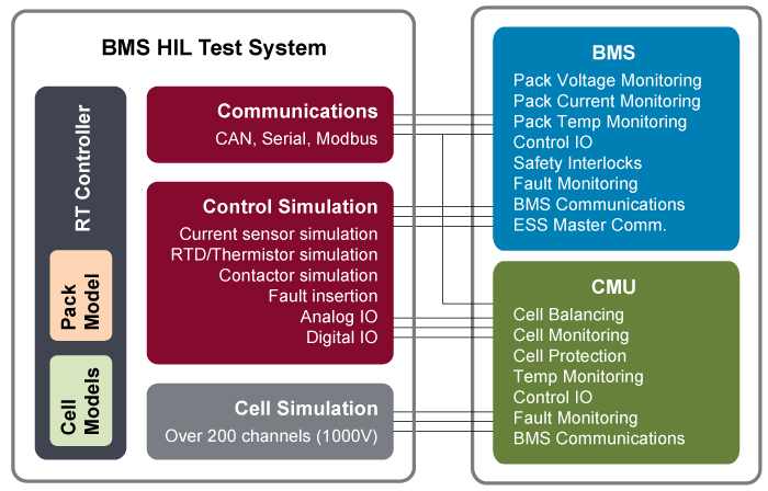
The BMS Hardware-in-the-Loop (HIL) Test System is a high performance platform providing all necessary input signals used for battery pack simulation. A real-time operating system executes complex cell and pack models commonly used for BMS algorithm development and firmware regression testing.
- Over 200 series connected cell voltage simulation
- Pack voltage simulation up to 1000 VDC
- Current and temperature sensor simulation
- BMS control IO and communication simulation
- Fault insertion and auxiliary system measurements
- Custom cell and pack model integration (Simulink, C++, LabVIEW, etc.)
- Software application for manual operation, automated test, and reporting
Use this form to configure your
Battery Pack Simulator
Battery Pack Simulator Configurator
The Battery Management Systems (BMS) Hardware-in-the-Loop (HIL) Test System provides a safe and efficient method for engineers to test BMS algorithms and system performance during the early stages of development for applications such as:
- Electric Vehicles/Plug-in HEVs
- High Power UPS/Grid Energy Storage Systems
- General Purpose Multi-cell Battery Stacks
Bloomy has designed a modular and configurable platform to accommodate the variety of battery input signals such as cell counts, sensors, IO, and communications required to simulate a BMS test atmosphere. Depending on the channel count, systems can range from a mobile industrial enclosure with high voltage safety to a desktop unit. The system software is a customized application built on the National Instruments VeriStand real-time test software environment, providing methods for configuring system models and test environment.
Trying to perform ESS, HASS, and HALT testing?
Visit the BMS Environmental Test System
The BMS HIL Test System is a modular platform, providing a unique configuration to test individual BMS devices and functionality.
The BMS HIL Test System is the ideal platform to use when developing and testing a battery management system and a wide range of battery-sensitive electronics. Benefits include:
- Provides a safe and efficient method of simulating a high voltage battery
- Implements irregular and dangerous physical battery conditions
- Improves quality of testing with repeatable stimulus
- Reduces test duration and cost by not using physical batteries
- Shortens development process through executing known test scenarios
The following specifications are standard. Systems can be customized to accommodate your requirements.
| Cell Channel Simulation | |
|---|---|
| Number of Channels | 12 / module |
| Max number of Modules | 20 (240 channels @ 4.2V) |
| Channel Type | Sink and Source |
| Voltage Range per cell | 0.0 to 5.0V |
| Voltage Resolution | 0.1 mV |
| Voltage Accuracy (Requires Remote Sense) | ±3 mV |
| Balancing Current Range* | ± 500.0 mA; output derates linearly under 2 V |
| Current Resolution | 0.1 mA |
| Current Accuracy | ±4 mA |
| Current Limiting Accuracy | ±10 mA |
| Common Mode Isolation | 1000 VDC |
| Cell Channel Readback | |
|---|---|
| Voltage Resolution | 0.1 mV |
| Voltage Accuracy | ±3 mV |
| Current Resolution | 0.1 mA |
| Current Accuracy | ±4 mA |
| Temperature Sensor Simulation | |
|---|---|
| Typical Signal Type* | Voltage Resistance |
| Number of Channels | 4 to 64 |
| Range | ±10V 2.5Ω – 1.5MΩ |
| Resolution | <1 mV 2Ω |
| Accuracy (typical) | 0.03% 0.2% |
| Current Sensor Simulation | |
|---|---|
| Typical Signal Type | Analog voltage |
| Number of Channels | 2 channel |
| Range | ± 10V |
| Resolution | 16 bit |
| Accuracy | ± 0.5% |
| Additional Signal Types | CAN communications |
| BMS Bus Voltage Simulation | |
|---|---|
| Number of Channels | 2 channel |
| Voltage Range* | 0 to 60V |
| Current Range* | 0 to 20A |
| Power Range | 850W |
| Communication Protocols | |
|---|---|
| Standard Protocol | High-speed CAN |
| Number of Ports | 2 |
| Baud Rate | 40 kbits/s to 1 Mbit/s |
| Additional Protocols | LIN, SPI, RS232, Modbus |
| Pack Voltage Simulation | |
|---|---|
| Number of Channels | 1 to 10 |
| Voltage Range* | Up to 1000 VDC |
| Output Power | 5W 30W 1500W |
| Resolution | 0.1V 0.1V 0.003V |
| Accuracy (typical) | 1-2% 1-2% 0.075% |
| BMS Control IO | |
|---|---|
| Number of Channels | Up to 32 input / 32 output |
| Voltage Range | 0 to 30V |
| Current Drive | Up to 150 mA |
| Common Mode Isolation | 30V bank-to-bank |
* Do you have special requirements for cell, bus, or pack voltage or current; isolation , temperature simulation, or communications? Contact us.
Bloomy use the latest versions of the National Instruments VeriStand and LabVIEW development environments to customize the application software based on final system hardware. Because all BMS units are unique, Bloomy has developed system level components to facilitate platform scalability and supportability to reduce software customization. Major application features:
- Graphical User interface: to ensure you get the most out of the system, a customized interface is provided to view full system status and perform all system control, test, report viewing, and configuration.
- Manual Control: complete operation of system channels and allows for value forcing, alarming, calibration, and stimulus generation.
- Automated Test: fully automated test environment, providing the ability to generate stimulus profiles (drive profiles) and test scenarios to complete BMS firmware regression testing.
- Communication Integration: integrate standard CAN and LIN automotive diagnostics or implement custom communication protocols used as feedback into models or measurement and reporting channels.
- Reporting: create test reports for system IO, communication capturing during manual or automated control.
- System Configuration: store all necessary hardware configuration information, software variables, IP address, report folders, model location, test stimulus profiles, and other critical station information.
- Model Execution: save, recall, and load custom models. Model execution is dependent on system IO, channel count, feedback, and the model itself. Typical pack model execution (complete system IO) is between 10Hz and 500Hz. Benchmarking is available.