
Battery HIL simulator for BMS development and validation
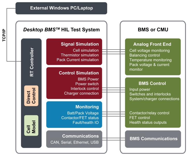
The Desktop BMS™ HIL Test System is perfect for BMS software, firmware, and hardware engineers who need to simulate battery cells and signals for testing a BMS or CMU in a convenient desk- or bench-top location. Integrating Bloomy’s industry-leading battery cell simulators, COTS instrumentation, and common DSUB connectors with Bloomy’s BMS HIL Test Software Architecture, the system can easily connect to a wide variety of BMSs and CMUs using basic screw terminal breakout boards. By bringing the rigor of the HIL lab onto convenient, personal desktops, The Desktop BMS™ HIL Test System helps maximize the productivity of multi-person battery engineering teams!
- Compact, rugged and transportable desktop form factor
- Simulates 12-36 battery cells with sink/ source characteristics
- Voltage-based thermistor and pack current simulation
- Optional bidirectional pack power
- Discrete IO control and monitoring
- Control and monitor BMS communications
- Intuitive UI with model-based or direct control of simulated signals
- Parametric 2nd order equivalent circuit cell model
- Real-time or Windows-based HIL execution
- Ethernet connectivity to external PC or laptop
- Multiple configurations to meet a wide variety of testing needs
The Desktop BMS™ HIL Test System provides a safe and efficient method for firmware developers and test engineers to test BMS algorithms and system performance during the early stages of development for applications such as:
- BMS software, firmware and hardware development
- BMS design validation testing
- Battery surrogate for subsystem integration testing
Need more channels?
Inquire about Bloomy’s FLEX BMS™ Validation System.
The Desktop BMS™ HIL Test System provides a compact configuration to test individual BMS devices and functionality.
The Desktop BMS™ HIL Test System is the ideal platform to use when developing and testing a battery management system and cell monitoring unit. Benefits include:
- Provides a safe and efficient method of simulating signals into the BMS and CMU Analog Front End (AFE)
- Quick connectivity with industry-standard DSUB connectors and breakout boards
- Portable form factor for easy transportation and storage
- Improves quality of testing with repeatable stimulus and test scenarios
- Reduces test duration and cost associated with using physical batteries
- Uses the same BMS HIL software architecture as Bloomy's larger rack-based BMS HIL test systems
The Desktop BMS™ HIL Test System comes in several standard configurations in a compact, heavy-duty rolling 6U or 8U rack for easy storage, transport, and shipping. See datasheet for all details. The following tables specify the typical signal configurations. Custom configurations are also available.
| Cell Channel Simulation | |
|---|---|
| Number of Channels | 12 / module |
| Max number of Modules | 2 (24 channels @ 4.2V) |
| Channel Type | Sink and Source |
| Voltage Range per cell | 0.0 to 5.0 V |
| Voltage Resolution | 0.1 mV |
| Voltage Accuracy (Requires Remote Sense) | ±3 mV |
| Balancing Current Range* | ± 500.0 mA; output derates linearly under 2 V |
| Current Resolution | 0.1 mA |
| Current Accuracy | ±4 mA |
| Current Limiting Accuracy | ±10 mA |
| Common mode isolation | 300VDC (limited by external DSUB connector) |
| Cell Channel Readback | |
|---|---|
| Voltage Resolution | 0.1 mV |
| Voltage Accuracy | ±3 mV |
| Current Resolution | 0.1 mA |
| Current Accuracy | ±4 mA |
| Temperature Sensor Simulation (Resistance) | |
|---|---|
| Typical Signal Type* | Variable Resistance |
| Number of Channels | 2 - 12 |
| Range | 16Ω to 160 kΩ |
| Error | 0.25% (enhanced mode) 0.01% to 10% (standard mode) |
| Temperature Sensor Simulation (Voltage) | |
|---|---|
| Typical Signal Type* | Analog Voltage |
| Number of Channels | 12 |
| Range | ± 10V |
| Resolution | 16 bit |
| Accuracy | ± 0.5% |
| Current Sensor Simulation | |
|---|---|
| Typical Signal Type | Analog voltage |
| Number of Channels | 2-4 channel |
| Range | ± 10V |
| Resolution | 16 bit |
| Accuracy | ± 0.5% |
| Isolation | Ground-referenced standard optional 250Vrms isolation per channel |
| General Purpose IO | |
|---|---|
| Analog Inputs | Up to 32 single ended ± 10V |
| High Voltage Analog Inputs | Up to 3 isolated ± 150V |
| Analog Outputs | Up to 6 ± 10V |
| TTL DIO | Up to 8 5V channels |
| Industrial DIO | Up to 16 inputs / 16 outputs, 12/24V logic levels |
| Relay dry contacts | 4 SPST, 60V, 1A |
| System Power | |
|---|---|
| Fixed power supplies | 5V, 12V, 24V standard |
| Programmable power supplies | Optional standard or bidirectional. Power, Voltage, Current TBD based on requirements |
| Communication Protocols | |
|---|---|
| RS232 | 1 port standard |
| RS485 | 1 port standard |
| USB | Standard |
| Ethernet | Standard |
| High-speed CAN | Optional (1 or 2 ports) |
* Do you have special requirements for cell, bus, or pack voltage or current; isolation , temperature simulation, or communications? Contact us.
Bloomy use the latest versions of the National Instruments VeriStand and LabVIEW development environments to customize the application software based on final system hardware. Because all BMS units are unique, Bloomy has developed system level components to facilitate platform scalability and supportability to reduce software customization. Major application features:
- Graphical User interface: to ensure you get the most out of the system, a customized interface is provided to view full system status and perform all system control, test, report viewing, and configuration.
- Manual Control: complete operation of system channels and allows for value forcing, alarming, calibration, and stimulus generation.
- Automated Test: fully automated test environment, providing the ability to generate stimulus profiles (drive profiles) and test scenarios to complete BMS firmware regression testing.
- Communication Integration: integrate standard CAN and LIN automotive diagnostics or implement custom communication protocols used as feedback into models or measurement and reporting channels.
- Reporting: create test reports for system IO, communication capturing during manual or automated control.
- System Configuration: store all necessary hardware configuration information, software variables, IP address, report folders, model location, test stimulus profiles, and other critical station information.
- Model Execution: Use Bloomy's parametric 2nd order equivalent circuit model, or pull in your own from Simulink, C/C++, or LabVIEW