Simplified evaluation of multiple battery management systems
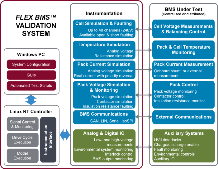
The FLEX BMS™ Validation System is a quick-connecting, highly flexible test system for rapid evaluation of centralized, single-board and distributed battery management systems. Utilizing Bloomy’s industry-leading battery cell simulators, COTS instrumentation, industry-standard connectors, and models that run in real-time, the FLEX BMS™ Validation System can easily be reconfigured to test a wide variety of BMSs. The FLEX BMS™ Validation System is used by national and regional safety and standards labs for certifying the BMS for a wide array of e-mobility products and applications.
- Up to 48 cells of simulation
- Voltage- or resistance-based thermistor simulation
- Simulate real pack current charging and discharging up to 600A through the BMS
- Simulate and monitor all BMS IO signals & communications
- Easily reconfigurable with standard DSub connectors and breakout boards
- Intuitive UI with model-based or direct IO control of simulated signals
Use this form to configure your
Battery Pack Simulator
The FLEX BMSTM Validation System allows electrification companies and test labs to rapidly and eoconomically evaluate the safety and performance of multiple battery management system designs for a wide array of products, ranging from electric vehicles to consumer electronics. Features include:
- Simulates battery voltage, current, and temperature signals, vehicle/system electronic signals and communications
- Ergonomic Signal Interface Panel provides quick and convenient access to simulation and monitoring signals
- Simple connectivity to the BMS under test through common, industry-standard connectors and breakout boards without the need for specialty tools
- Real-time, deterministic execution of models and controls using embedded Linux Real-Time controller
- Supports standard as well as customer-proprietary models developed using The Mathworks Simulink®, C/C++ and LabVIEW
- Automated test case development and execution, with templates for common BMS test scenarios
- User-friendly graphical BMS interface provides interactive control of model execution and direct manual control and monitoring of all signals
- Uses NI VeriStand and NI TestStand commercial, off-the-shelf real-time engine and test executive, with support for Python scripting
Applications include:
- Rapid prototyping and product development - quickly "breadboard" test multiple different variants or "spins" of the BMS hardware, software and/or firmware.
- Application testing - evaluate the configuration, performance and safety of several sample or prototype BMSs, from the same or different third-party suppliers, under the same conditions in a simulated application.
- Regression testing - run comprehensive test scripts for the evaluation of short- and long-term performance and reliability of different BMS hardware, software and firmware updates.
Need to simulate more than 48 cells?
Visit BMS HIL Test System to consider our full-featured BMS HIL System.
The FLEX BMS™ Validation System is the ideal platform to use for rapid evaluation of centralized, single-board and distributed battery management systems. Benefits include:
- Easily connect a BMS to simulation signals without the need for specialty tools and cable harnesses
- Intuitively interact with the BMS through a user-configurable GUI
- Test multiple BMS designs and software revisions using a safe and repeatable test stimulus
- Readily self-maintained using best-in-class commercial, off-the-shelf hardware and software
- Focus valuable engineering resources on developing and testing the BMS, not designing the test equipment
- Reduce time-to-market of new BMS designs and configurations
- Ergonomic, flexible and easy-to-use
The following specifications are standard. Systems can be customized to accommodate your requirements.
| Signal Type | Qty | Description | Details |
|---|---|---|---|
| Cell Simulation | 12-48 | Simulation of individual cells | 0-5VDC, Sink/Source 500mA ±3mV accuracy, 0.1mV resolution |
| Temperature Simulation | 4-32 | Simulation of cell/pack temperatures | Analog Voltage (±10V) Resistance (0-65kΩ) |
| Pack Current Simulation | 1-2 | Simulation of full pack current (eg 400A) | 1-4 Analog Voltage (±10V) (isolated or non-isolated)
1x Programmable PS (30A, 60A, 150A, 600A options) with polarity reversing relays for charge/discharge |
| Vehicle Discretes | 2-8 | Controlling ignition, interlock, enable, CAN power | Fixed power supply with 5, 12, or 24V digital output control |
| Insulation Resistance Sim | 1-2 | Simulating HV resistance to test BMS monitor circuits | Fixed resistors with high voltage switching |
| Comms | 1-4 | BMS-Vehicle, Module, etc. | CAN, LIN, Serial, IsoSPI |
| Contactors | 2-4 | Simulation of contactors to verify BMS control | Real contactors w/faulting or HV DCDC with modeling |
| Misc. BMS IO | 4-12 | Misc. analog/digital inputs and outputs to/from BMS | Analog/digital inputs & outputs for simulation/monitoring |
| Vehicle/CAN Power | 1 | 5, 12V or 24V main power | Available as fixed or Programmable Power Supply |
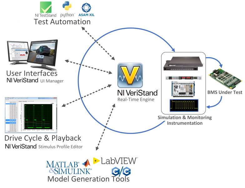
The FLEX BMS™ Validation System is controlled by Bloomy's BMS HIL Software Architecture, a customizable, integrated set of test extensions for NI VeriStand and TestStand which reduce development time and increase BMS HIL test functionality. The architecture enables a wide range of BMS test methodologies, from manual diagnostic control and monitoring, to automated sequencing for hardware and firmware validation, as well as full model-based validation of control algorithms. Operators can run multiple different BMS test sequences and can quickly switch between the various testing methodologies on-the-fly. Major application features:
- Real-Time Closed-Loop Control: Control and monitor all signals, execute models, and communicate with the BMS at real-time deterministic update rates of 100Hz - 2kHz update rates (depending on channel count and processor power)
- BMS Communication Integration: integrate CAN, Serial, SPI, or custom communication protocols to monitor BMS status, Diagnostic Trouble Codes, SOC, SOH, cell & pack voltages, currents, and temperatures
- Model Integration: incorporate cell chemistry and other plant models in Simulink, LabVIEW, or C/C++ to make the system behave like a true battery surrogate. Provide your own, or use Bloomy's LabVIEW model template.
- Software-selectable Output Control: switch between direct IO control and model-based control with the flip of a UI switch
- Graphical User interface: customizable GUIs provide access to directly control and monitor the system's signals and communiations; includes screens for instrument control, BMS interfacing, and model controls
- Automated Test: fully automated test environment, with customizeable templates for system and BMS interface, Safe Operating Area (SOA) functional tests, and model-based testing
- Drive Cycle Testing: implement engineered drive cycles or play back pre-recorded data though direct IO control or model-based control
- Reporting: create test reports for automated tests, or log high-speed real-time data to TDMS format for post-processing.
- System Configuration: store all necessary hardware configuration information, software variables, IP address, report folders, model location, test stimulus profiles, and other critical station information.