A Test Engineer's Perspective
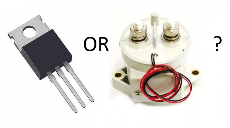
During a recent social media post, a reader inquired: "I am interested in your thoughts on MOSFETs (or IGBTs) vs. Contactors in a BMS."
While I am by no means an expert on the design of a battery management system (BMS), I have had the opportunity to test and evaluate a very large variety of BMSs, from small 6s-12s single-board centralized BMSs up to large distributed multi-module EV and grid storage BMSs.
In general, MOSFETs (often shortened to just FETs) and contactors serve the same purpose - to connect and disconnect the battery power to a load or charger. Most of the time, this is a planned process when starting up, shutting down, or charging a battery. However, these methods are also used to disconnect the battery's load if the Safe Operating Area (SOA) of the battery is exceeded.
MOSFETs and contactors each have their own specific benefits and issues.
MOSFETs fail shorted... that is until they completely melt down, at which point they do open up. Not necessarily safe, and certainly not without undesirable consequences. FETs also have a distinct voltage drop across them, directly proportional to current. This generates substantial heat requiring proper thermal management in the form of heat sinks. FETs also are not typically designed for 100s of amps on their own, so a typical FET-based design will require many FETs in parallel to handle the power (in some cases I've seen 6-10 on a single board). On the other hand, they are solid state, so they are relatively inexpensive and have a very high cycle-life count (on the order of 109 or so cycles) due to the lack of moving parts.
Contactors on the other hand are electro-mechanical devices that can wear out over time. Contactors can wear out mechanically, effectivly 'slowing down' their engagement. They can also build up carbon on contacts causing increased resistance over time. Furthermore, directly engaging a high power load can cause a contactor to weld shut, failing shorted similar to a FET. Fortunately, this is often solved by use of a precharge resistor - which provides a higher impedance connection while engaging the contactors, balancing the voltage on either side of the main power contactors - reducing the likelihood of arcing. Many contactors also have auxiliary feedback circuits that allow the BMS to detect failures to engage or disengage.
As far as applications go:
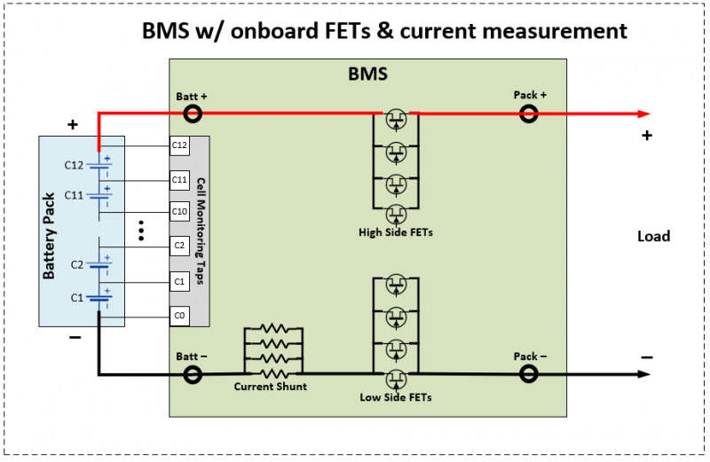
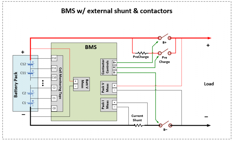
Typically, I've seen MOSFETs on smaller centralized, single-board BMSs, where the pack power actually runs through the BMS PCBA. These tend to be lower power (12-48V, and no more than 20 or 30A), and low cost. They are generally used for very inexpensive applications where power requirements are relatively low (high volume, low cost consumer electronics, such as USB power bricks, toys, wearables, etc). Contactors tend to be used on both centralized and distributed BMSs for higher power and higly regulated applications. Whether the BMS is centralized (single board) or distributed (modules and a pack controller), the battery power is routed externally from the BMS, which only monitors the current and controls the external contactors.
Because I am a test engineer, I think of things most from that perspective. Our test systems for centralized BMSs with MOSFETs are the ones which typically use a high-current supply to simulate pack current through the BMS. BMSs with external contactor control can more easily be simulated using basic, lower cost analog and digital IO. The interesting point here is that the centralized BMSs with current running through the board which are generally intended for lower-cost applications actually require more expensive equipment to properly test. In the SOA tests, the main difference is what you are detecting for "Fault" state when you exceed the SOA. With a centralized BMS containing onboard FETs, we typically monitor the voltage/current output from the BMS to detect when the BMS goes into a fault state. On external contactor-based BMSs, we typically monitor the discrete outputs from the BMS that would be used to control the contactors. Either way, the result is the same: get the BMS into a known good operating state, then exceed each SOA to ensure it does what it was meant to do - protect the user and the product/vehicle from the high power of the battery.
Related links
Battery management system testing equipment
Free downloadable BMS testing resources
- ggothing's blog
- Log in or register to post comments