MIL-STD-1553B is a low-speed avionics data protocol frequently used in aircraft for communication between different line-replaceable units (LRUs). Hardware-in-the-loop (HIL) simulators and systems integration labs (SILs) frequently simulate MIL-STD-1553B networks using devices such as Bloomy's 1553B C Series module. This article presents a high-level overview of MIL-STD-1553B communications and implementation.
Physical Layer
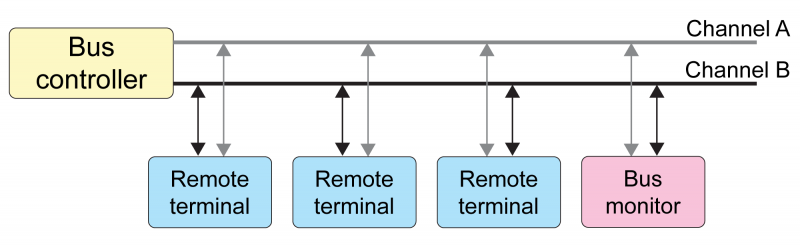
MIL-STD-1553B is typically implemented as a dual-redundant network consisting of a primary bus (Bus A) and secondary bus (Bus B). Messages are normally transmitted on the primary bus, with the secondary bus as a fallback. The network consists of a central spine (the bus) with a 78 Ohm termination resistor at either end and network components connected to the network with transformer-coupled stubs.
Data is transmitted in Manchester encoded words consisting of a 3-bit sync, 16 data bits, and an odd parity bit. MIL-STD-1553B is a 1 megabit bus, so a single word takes 20 µs. Sync and parity bits are not typically exposed to higher-level drivers, though they may sometimes be manipulated for fault injection.
Network Components
An entity on a MIL-STD-1553B network is classified as a Bus Controller (BC), Remote Terminal (RT), or Bus Monitor (BM). These are described below:
| Component | Max Number on Bus | Description |
| Bus Controller | 1 | Transmits or requests data from specific subaddresses of specific Remote Terminals, typically on a cyclic message schedule. The Bus Controller may transmit on either the primary or secondary bus and is frequently set up to retry messages on the secondary bus if a Remote Terminal fails to respond on the primary bus. |
| Remote Terminal | 30 | A MIL-STD-1553B bus may have up to 30 Remote Terminals. Each Remote Terminal (RT) has up to 30 transmit subaddresses and up to 30 receive subaddresses. (So RT 1 may have both Tx SA 1 and Rx SA 1.) An RT subaddress responds to transmit or receive commands from the Bus Controller with the requested data in the case of a transmit command, or by receiving data from the BC and sending back a status word in response in the case of a receive command. RTs are silent unless directly addressed by a bus controller. RT 0 and RT 31 are typically reserved for broadcast messages, and SA 0 and 31 are typically reserved for mode codes. See the “Messages” section below for details. |
| Bus Monitor | N/A | A Bus Monitor may optionally exist on a MIL-STD-1553B bus to monitor traffic without generating any of its own. A Bus Monitor can typically be configured to filter and monitor only messages of interest, sorting by Remote Terminal, subaddress, and transmit/receive. |
Messages
Basic MIL-STD-1553B messages can be designated as “transmit” or “receive”. These terms are from the point of view of a Remote Terminal – i.e., “transmit” is the Bus Controller requesting the RT to transmit data, while “receive” is the RT receiving data from the Bus Controller. In all cases, the Bus Controller initiates the transaction.
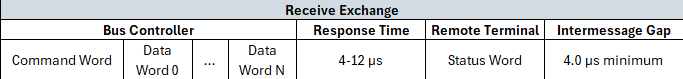
In a transmit message, the Bus Controller will send out a command word addressing the RT and subaddress to request data. The RT will respond with a status word, followed by 1 to 32 data words.
![]()
In a receive message exchange, the Bus Controller will send out a command word addressing the RT and subaddress to receive data, followed by 1 to 32 data words. The RT will respond with a status word.
The command word transmitted by the Bus Controller addresses a message to a specific Remote Terminal and subaddress and identifies the type of message (transmit/receive) and number of data words to expect.

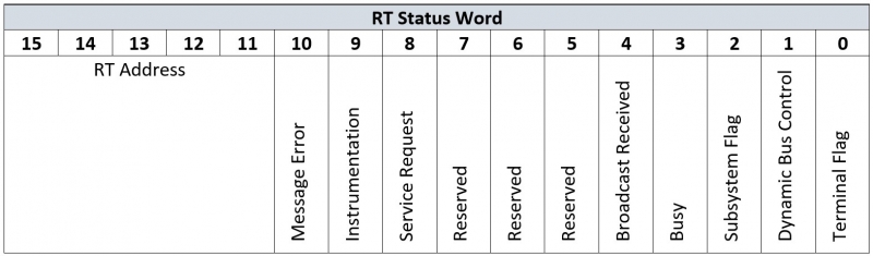
The RT status word identifies the responding Remote Terminal to the Bus Controller and carries a number of flags indicating the RT’s current condition.
In addition to the standard transmit and receive messages, there are a number of special use message types.
- Broadcast Messages - The Bus Controller sends a command word with an RT address of 0 or 31. This message is received by the appropriate subaddress of every RT on the bus. Remote Terminals do not reply to broadcast messages in order to avoid bus collisions.
- RT-RT Messages - The Bus Controller instructs a Remote Terminal to send a message to another Remote Terminal by sending first the command word for the receiving RT, followed by the command word for the transmitting RT.
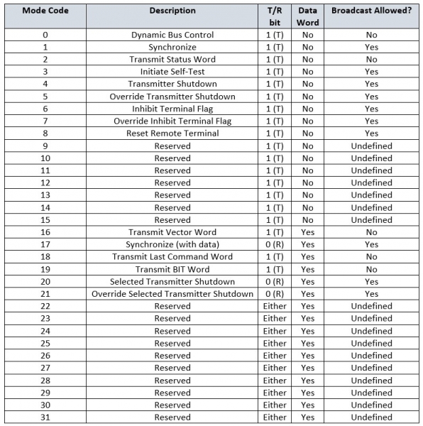
- Mode Codes - Mode codes are a set of 32 possible bus control commands. They may have 0 or 1 data words associated with them and are meant to trigger specific defined behaviors on a Remote Terminal. To transmit a mode code, the BC sends a command word with a subaddress of 0 or 31. The word count field then contains the mode code. A table of possible mode codes is shown below.
Message Scheduling
A Bus Controller typically sends out messages in a cyclic schedule. This schedule is sometimes called a major frame, and the time it takes to complete the major frame time. A major frame contains a number of minor frames, each of which contains one or more messages. The time between messages in a minor frame is dictated by the intermessage gap time, which is typically settable at the message level. Frames themselves are sent at regular intervals over the course of a major frame. The frequency of these intervals is the minor frame rate, which acts as a kind of metronome for the major frame. Suppose, for example, that you have Message A, which should be transmitted at 20 Hz, Message B, which should be transmitted at 10 Hz, and Message C, which should be transmitted at 5 Hz. To accomplish this, you could construct the following minor frames:

The fastest message (Message A) needs to go at 20 Hz (or a period of 50 ms), so this will dictate the minor frame rate. The resulting major frame will look like this:

Since the minor frame rate is 20 Hz, each minor frame is allotted 50 ms to complete. Message A will execute once every 50 ms (at 20 Hz), since it is contained in Minor Frames 1, 2, and 3. Message B will execute once every 100 ms (10 Hz) since it is contained in Minor Frame 1 and Minor Frame 2. Message C will execute once every 200 ms (5 Hz), since it is contained only in Minor Frame 1. The entire major frame takes 200 ms to complete.
In addition to scheduled messages, a Bus Controller can also send aperiodic messages. These come in two flavors:
- High priority aperiodic messages will be inserted into the next gap between scheduled messages.
- Low priority aperiodic messages will be inserted at the end of a minor frame (which usually has a substantial dead to allow for this).
More Information
Bloomy provides hardware, software as well as in-depth expertise for implementing the MIL-STD-1553B avionics bus in simulation system applications using NI LabVIEW Real Time, VeriStand, CompactRIO as well as PXI. For more information, please visit the related links below or contact us.
Related Links